The HLM engines are homebuilt engines which are designed to meet the special demands of control line combat competition engines. Father of this engines is Lothar. As a teenager he was strongly influenced by the CTM-Team. During his high school time he had to work on lathes and mills and took the chance to make a CTM-crankshaft by himself. Jonny (the famous manufacturer of the CTM engines) gave him many helpful tips. Con-rods, venturis and glow-plug inserts were produced on a little clockmaker lathe at home and his slightly modified CTM-engines were running very well. After the intake-restriction rule got valid in 1988, the CTM-engines were not able to keep up with the NELSON, USE and the upcomming russian engines. Improvements of the performance of the CTM engines seemed to be impossible.
In autumn 1988 Lothar decided to build his first own engine, the HLM-1. Due to the fact that mid air collisions and ground hits are not avoidable, it should be an engine with rear intake to prevent dirt contamination of the high precision inside of the engine as in case with front intake engines. In Lothars opinion, integral cylinders are the optimum solution to get maximum stiffness against warping and optimized heat transfer to the cooling fins. A right hand side exhaust with the possibility to mount a silencer and a strong crankshaft should be further features of this engine. The idea was: putting the best parts together in one engine should result in the most powerful one. The cylinder was ordered from JHP motorparts which were selling the USE parts at this time and the rear intake was ordered from Henry Nelson. The crankcase was made from an annealed sand cast aluminiun alloy (AlSi10Mg) with milled scavenging ports. The crankshaft was made from an annealed steel with the german alloy code 30 CrNiMo8. It was working in a 12x24x6 mm rear bearing and a 8x16x5 mm front bearing. The propeller screw (M5 thread, 30 mm long) meets the crankshaft thread behind the front bearing to avoid tensile and multiaxial stress concentration in the score behind the front bearing. A very rigid conrod (28 mm from pin to pin) with a bronze bushing in the big end was used to translate the piston forces into torque.
First flight was at the Ljimfords Competition 1989 in denmark. Although one year of experimental work was spent on this engine, it was not possible to get nearly the same power out than from current ones . The bad results created the growing wish to get more knowledge about the processes inside our engines and forced the decision to make in-cylinder and crankcase pressure measurements in Lothars final work at the Fachhochschule München to get the degree of a Diplom Ingenieur.
The HLM-V1 was made for engine test purposes in summer 1990, because all available engines exept from the “Mockba” had a combustion chamber which was screwed down with a threaded ring and made it impossible to integrate a pressure transducer in the cylinder head. The crankshaft and the conrod was taken from the HLM-1 whereas all the other parts exept the Nelson rear intake and the liner with piston were machined. The liner was a standard LST (three chanel, chromed brass).
The HLM-V2 was not realised. It should get a fully machined crankcase, but the delivered aluminium alloy was not the ordered one and Lothar decided to make a steel mould for casting the (HLM-V3) crankcase.
Pouring liquid aluminium in the mold as it was seen at PAW, was not the way to get usable crankcases. A test cast, done by a professional factory to investigate the quality of the solidification regime was built up to the only one HLM-V3. This engine had milled scavenging chanels and was fitted with the original HLM-1 crankshaft. The integral cylinder was bought from Jura Arsentijew who produced a series to replace USE cylinders and the rear intake system was taken from NELSON. This engine showed a desireable power potential, but the crankcase breaked during engine optimisation.
After the good experiences with the HLM-V3 the HLM-V4 was developed. To avoid fracture of the crankcase it should be machined from a strong aluminium alloy and a new crankcase design should avoid stress concentration in front of the rear ball bearing (if we consider the crankcase around the rear ball bearing as a ring which is radial elastic and the crankcase in front of the rear ball bearing as a shim which can be considered as radial stiff, we will get a high stress concentration between ring and shim in case of radial loads). Four crankcases of this engine type were made. All other parts were taken from the HLM-V3. The serial number two with a selfmade rear intake was getting a real successful engine. It was slightly faster than Lothars AKM engines but it was difficult to adjust for maximum power especially in tight maneuvers. This engine was used successful for qualification in 1996 and during the European Championships 1997.
A friend of Robert, working in a professional casting factory, casted some crankcases from the HLM-V3 crankcase mould. The engine which was built from this crankcases was the HLM-V5. Its difference to the HLM-V3 is a 10 mm crankshaft, running in a 10x19x5 mm rear bearing. Only one engine (from two) was finished in 1996. It was working well and is now fitted with a L&L cylinder.
The L&L engine was built in cooperation with Loet in 1997/1998. The mould for the die cast crankcase was turned out by Lothar whereas Loet has done all the milling work. The first 17 wax castings were rear intake crankcases and after milling down a small wall in the mould all further castings were front intake crankcases.
Loet finished his engine in 1998, but his engine showed vibration problems which were very difficult to locate. A comparison of the torsional stiffness between Loets 12 mm diameter crankshaft (with radial slot for front intake) and Lothars 10 mm diameter crankshaft for rear intake showed that the torsional stiffness of Lothars crankshaft was 2.5 times higher although it had a smaller diameter! But the real reason for the vibration problems were not found. Loet got better results in using the crankshaft from the MMB-Caziol engine.
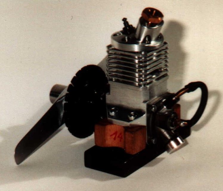
Lothars L&L engines are fitted with the above mentioned 10 mm diameter crankshaft, running in a 10x19x5 mm rear bearing like the HLM-V5. 6 L&L rear intake crankcases were machined in spring 1999, 5 were finished. The photo shows a L&L engine with (AKM) cylinder liner and piston.
In the last flight tests of a L&L it was faster than an AKM which served as a reference. This L&L was damaged during this test and Lothar decided on the way home to build the HLM-V6 (with a steel crankcase).
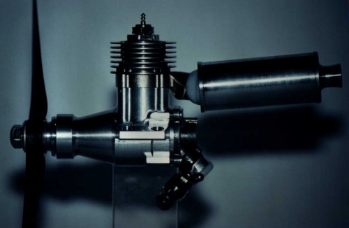
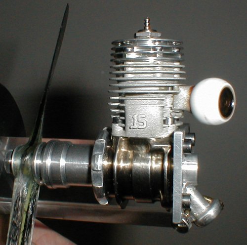
The HLM-V6 engine is using cylinders which Lothar got from Rob Metkemejer during casting of the L&L crankcases for the promise to build up a combat engine with these cylinders. Rob built this cylinder for his team race engine which are not fitted with silencers. Because combat engines requires a silencer, an adapter was glued to the cylinder. The crankshaft was taken from the L&L engine, but it is running in a 10x22x6 mm rear bearing. To save weight, the engine mounts are integrated in the rear intake backplate.
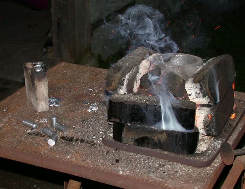
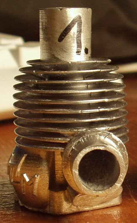
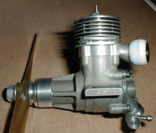
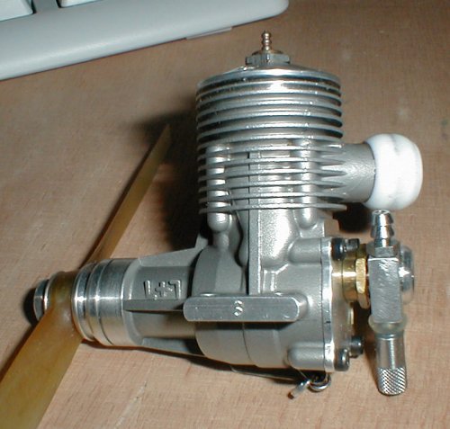
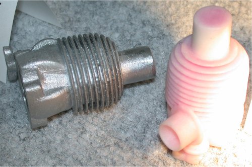
The latest modification of the HLM-V6 is shown in the photo below. It is a full integral cylinder which was mannufactured by BARTZ & SCHALK using rapid prototyping methods (laser sintering) to get the model. It was precision casted by RAPID METAL Technologies GmbH.
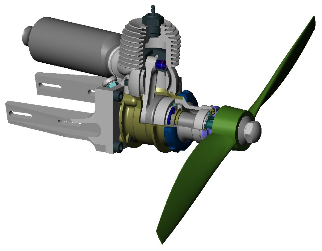
A screenshot of the CAD-model of this engine is shown below.