Engine research is one essential tool to improve the performance of engines without wasting a lot of time using the try & error method. Dr.Gordon P. Blair f.e. (Lothar call him “Two Stroke Pope”) is one who shows how to do engine research in the best possible manner.
A special situation for control line combat model engine builders was caused in 1988 after the CIAM introduced the first rule into the international control line combat reglement which should only reduce the power output of the engines. The power of the current engines was considerably reduced, but also the power difference between engines of the same and different types were increased. This situation and Lothars bad experience with his first homebuilt engine, which was built in 1989 according to the current rules initiated the big wish to get the knowledge about what is really going on inside our engines. He decided to make in-cylinder and crankcase pressure measurements in his final work at the Fachhochschule München to get the degree of a Diplom Ingenieur.
The title of this work was:
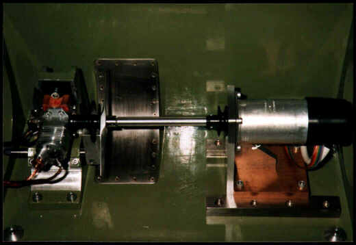
The engine test bench on which this work was done is shown in the picture below. It shows the arrangement of Lothars homebuilt HLM-V-1 engine, the special torsional coupling shaft and the starter and brake-dynamometer brushless motor.
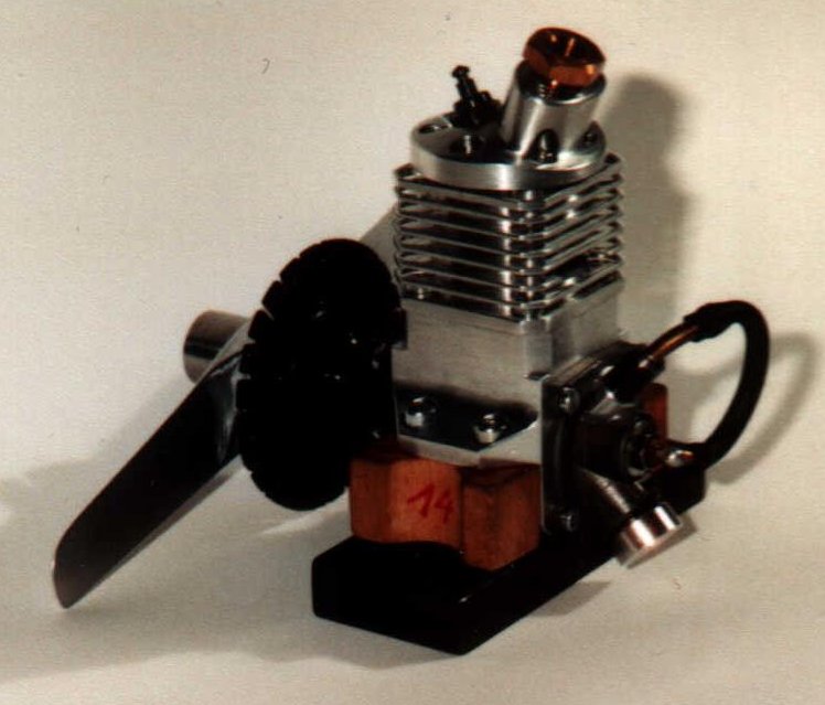
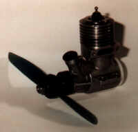
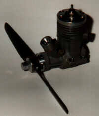
The engines shown on the pictures below were used to make the in-cylinder and crankcase pressure measurements.
Engines fitting the requirements of the reglement of the international control line combat competition events are high speed internal combustion two stroke engines with a swept volume of 2.5 cm^3 and an intake restrictor of 4 mm diameter. The methanol based fuel must contain 20% castor oil and 10% nitromethane. No silencing devices were required at this time.
 |
 |
 |
A short overview about the results of this work is shown below:
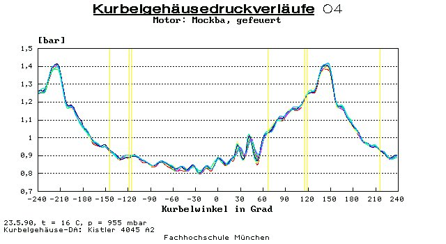
Fig. 1 shows the crankcase pressure versus crank angle over five revolutions at an engine speed of 25200/min. Zero deg. crank angle indicates TDC. We can see pressure fluctuations which are very repetitive with every revolution and are therefore no error signals from the pressure transducer. After transfer port opens at 118 deg. crank angle we can recognise a backflow of exhaust gas into the transfer ports.
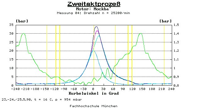
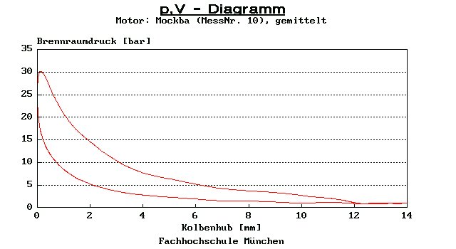
In Fig. 2 we can see the crankcase pressure (average of 10 revolutions) in green, the motored, TDC-symmetric (blue) and three fired in-cylinder pressure measurements (light blue, purpur and dark blue).
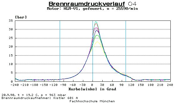
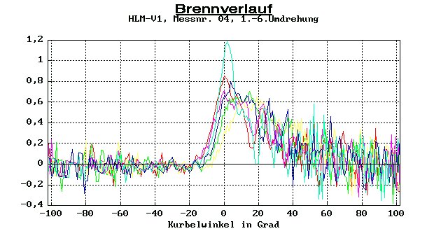
The cylinder pressure measurement over six revolutions is shown in Fig. 4. The heat release rate calculated from this pressure reading is shown in Fig.5. The calculation of the heat release rate is very sensitive at low pressure differentials which results in high signal noises during compression and expansion stroke. The colour of the curves between pressure measurement and heat release rate refers to each other.
The Diagramm of Fig. 6 shows crankcase and cylinder pressure readings of an Irvine .15 at different conditions:
(This Irvine .15 had no intake restriction and the timing was optimised for operation with a tuned pipe; all graphs show the average of several revolutions)
Green graph: crankcase pressure, motored condition at 12763/min
Red graph: cylinder pressure, motored condition at 12763/min
Dark blue graph: crankcase pressure, fired condition at 23750/min without tuned pipe
Purpur graph: cylinder pressure, fired condition at 23750/min without tuned pipe
Blue graph: crankcase pressure, fired condition at 36154/min with tuned pipe
Light blue graph: cylinder pressure, fired condition at 33400/min with tuned pipe
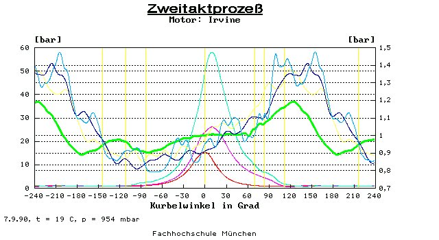
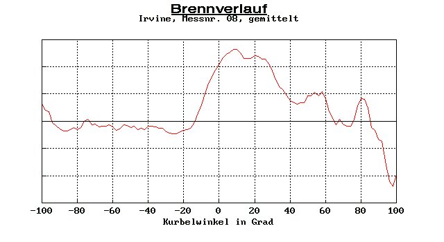
Fig. 7 shows the heat release rate calculated from the above pressure reading (light blue graph) at 33400/min with tuned pipe.